Numerical diffraction propagation#
Lentil uses Fourier transform-based algorithms to numerically model the
propagation of an electromagnetic field through an optical system. The
electromagnetic field is represented by a Wavefront object which stores the
complex amplitude of the field at a discretely sampled grid of points. The
optical system is represented by a set of Plane objects which the wavefront
interacts with as it propagates through the system.
Note
This section of the User Guide assumes some understanding of physical and Fourier optics. In-depth mathematical background and an extensive discussion of the validity of each diffraction approximation is available in [1].
Numerical diffraction propagation#
Lentil numerically models diffraction by propagating a Wavefront object
through any number of Plane objects representing an optical system. This
propagation always follows the same basic flow:
Create a new wavefront#
A Wavefront represents a monochromatic, discretely sampled complex field
that may propagate through space. By default, when a new Wavefront is
constructed it represents an infinite plane wave (complex field = 1+0j).
Note that “infinite” in this case really just means that the wavefront field
is broadcastable to any shape
necessary.
>>> w1 = lentil.Wavefront(wavelength=650e-9)
>>> w1.field
1+0j
>>> w1.focal_length
inf
Propagate the wavefront through a plane#
The planes that describe an optical system typically modify a propagating
wavefront in some way. By multiplying a Wavefront and a Plane together, a
new Wavefront is returned representing the the complex field after
propagating through the plane:
>>> pupil = lentil.Pupil(amplitude=lentil.circle((256, 256), 120),
...                      pixelscale=1/240, focal_length=10)
>>> w2 = w1 * pupil
Note the complex field of w2 now clearly shows the effect of propagating through the
circular aperture of pupil:
>>> plt.imshow(np.abs(w2.field))
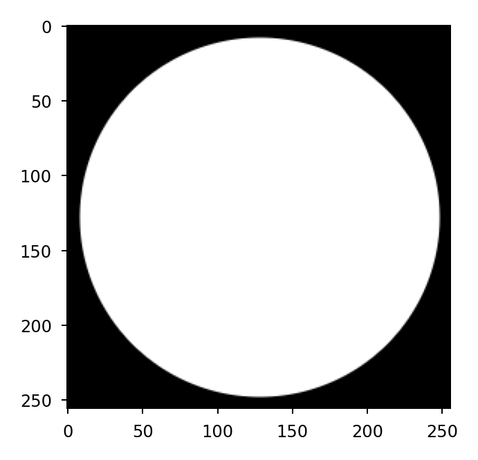
Additionally, because w2 was propagated through a Pupil plane, it has inherited the
pupil’s focal length:
>>> w2.focal_length
10
Note
Additional details on the plane-wavefront interaction can be found in How a plane affects a wavefront.
Propagate the wavefront to the next plane#
The table below describes what propagation method (or general transformation)
should be performed based on the wavefront and plane ptype:
Wavefront |
Plane |
Method |
|---|---|---|
|
|
|
|
|
|
|
|
Flip, resample, or none |
|
|
Flip, resample, or none |
|
|
Far field propagation not supported |
Note
When propagating between like planes (pupil to pupil or image to image), no additional diffraction propagation step is required.
Numerical diffraction propagations are defined by the following attributes:
pixelscale- the spatial sampling of the output planeshape- the shape of the output planeprop_shape- the shape of the propagation plane. See shape vs prop_shape for additional details.oversample- the number of times to oversample the output plane. See the section on sampling considerations for more details.
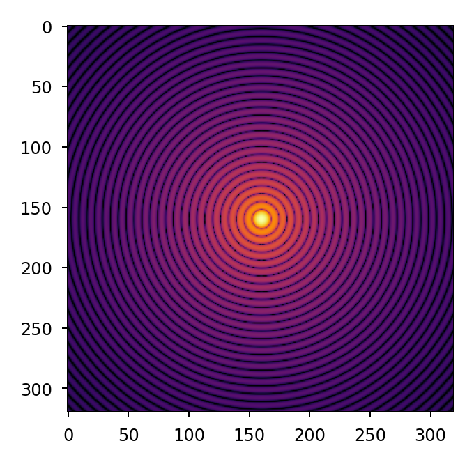
For example, to propagate a Wavefront from a Pupil to an Image plane:
>>> w2 = lentil.propagate_dft(w2, pixelscale=5e-6, shape=(64,64), oversample=5)
>>> plt.imshow(w2.intensity, norm='log', cmap='inferno', vmin=1e-4)
Propagate through remainder of model#
If multiple planes are required to model the desired optical system, the steps
described above should be repeated until the Wavefront has been propagated
through all of the planes.
Broadband (multi-wavelength) propagations#
The steps outlined above propagate a single monochromatic Wavefront through an
optical system. The example below performs the same operation for multiple
different wavelengths and accumulates the resulting image plane intensity:
pupil = lentil.Pupil(amplitude=lentil.circle((256, 256), 120),
                     pixelscale=1/240, focal_length=10)

wavelengths = np.arange(450, 650, 10)*1e-9
img = np.zeros((320,320))

for wl in wavelengths:
    w = lentil.Wavefront(wl)
    w = w * pupil
    w = lentil.propagate_dft(w, pixelscale=5e-6, shape=(64,64), oversample=5)
    img += w.intensity

plt.imshow(img, norm='log', cmap='inferno', vmin=1e-4)
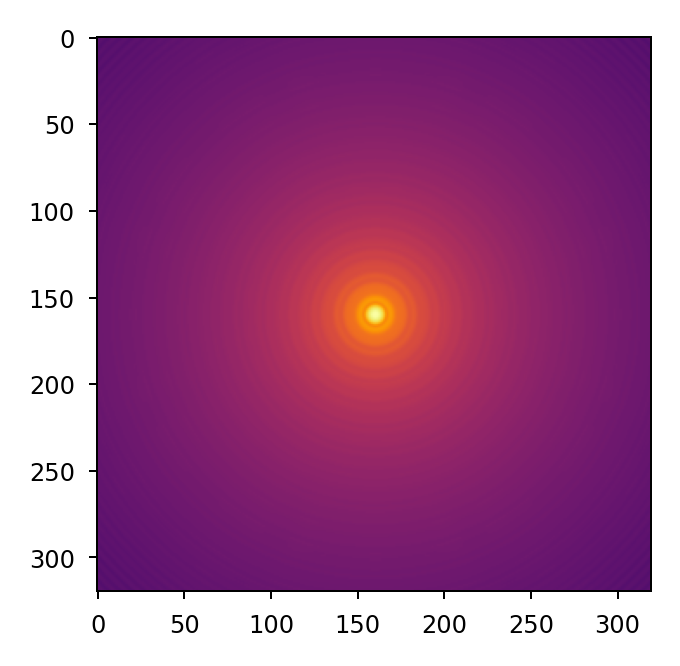
Keep in mind the output img array must be sized to accommodate the oversampled
wavefront intensity given by shape * oversample.
Increasing broadband propagation performance#
Using Wavefront.insert()#
Each time wavefront.field or wavefront.intensity is accessed, a new Numpy
array of zeros with shape = wavefront.shape is allocated. It is possible to
avoid repeatedly allocating large arrays of zeros when accumulating the result of
a broadband propagation by using Wavefront.insert() instead. This can result
in significant performance gains, particularly when wavefront.shape is large.
The above example can be rewritten to use Wavefront.insert() instead:
for wl in wavelengths:
    w = lentil.Wavefront(wl)
    w = w * pupil
    w = lentil.propagate_dft(w, pixelscale=5e-6, shape=(64,64),
                             oversample=5)
    img = w.insert(img)
Using Plane.freeze()#
Some planes implement custom opd logic that computes the
return value each time the attribute (more accurately, property) is accessed.
When using these planes in a broadband propagation performance will suffer
since the opd attribute is accessed for each wavelength.
Because the underlying OPD value is static for the duration of a propagation,
an opportunity exists to use a cached value which can provide a substantial
performance boost. Plane.freeze() provides this cache mechanism. Again
modifying the above example:
frozen_pupil = pupil.freeze()

for wl in wavelengths:
    w = lentil.Wavefront(wl)
    w = w * frozen_pupil  # cached OPD value is used here
    w = lentil.propagate_dft(w, pixelscale=5e-6, shape=(64,64), oversample=5)
    img += w.intensity
Sampling considerations#
The accuracy of a numerical diffraction simulation depends on adequately sampling the input and output planes. The sections below describe how to select appropriate sampling for these planes and how to configure the propagations to avoid the introduction of numerical artifacts.
Ensuring Nyquist-sampled output#
The relationship between spatial sampling in the input plane and output plane is defined by \(Q\) and should be at least 2 in numerical simulations to ensure the output plane is Nyquist-sampled for intensity:
where \(lambda\) is propagation wavelength, \(F/\#\) is focal length divided by diameter, and \(du\) is output plane spatial sampling. High-frequency ailiasing is clearly apparent in propagations where \(Q < 1.5\) and still visibile to those with a keen eye when \(1.5 < Q < 2\):

In cases where the optical system \(Q\) is less than 2, the simulation
fidelity should be increased by oversampling to avoid ailiasing. For a given
imaging system, the system’s \(F/\#\), output plane sampling, and
propagation wavelength(s) will be fixed values. As a result, \(Q\) can
only be increased in a discrete propagation by introducing an oversample
factor that effectively decreases the output plane sampling \(du\). In
order to view the results of a propagation at native system sampling, the
oversampled output plane must be resampled or rebinned.
Note
oversample should always be chosen to ensure \(Q > 2\) for accurate
propagation results.
Avoiding periodic wraparound#

shape vs prop_shape#
Lentil’s propagation methods have two arguments for controlling the shape of
the propagation output: shape and prop_shape.
shape specifies the shape of the entire output plane while prop_shape
specifies the shape of the propagation result. If prop_shape is not
specified, it defaults to shape. The propagation result is placed in the
appropriate location in the (potentially larger) output plane when a Wavefront
field or intensity
attribute is accessed.
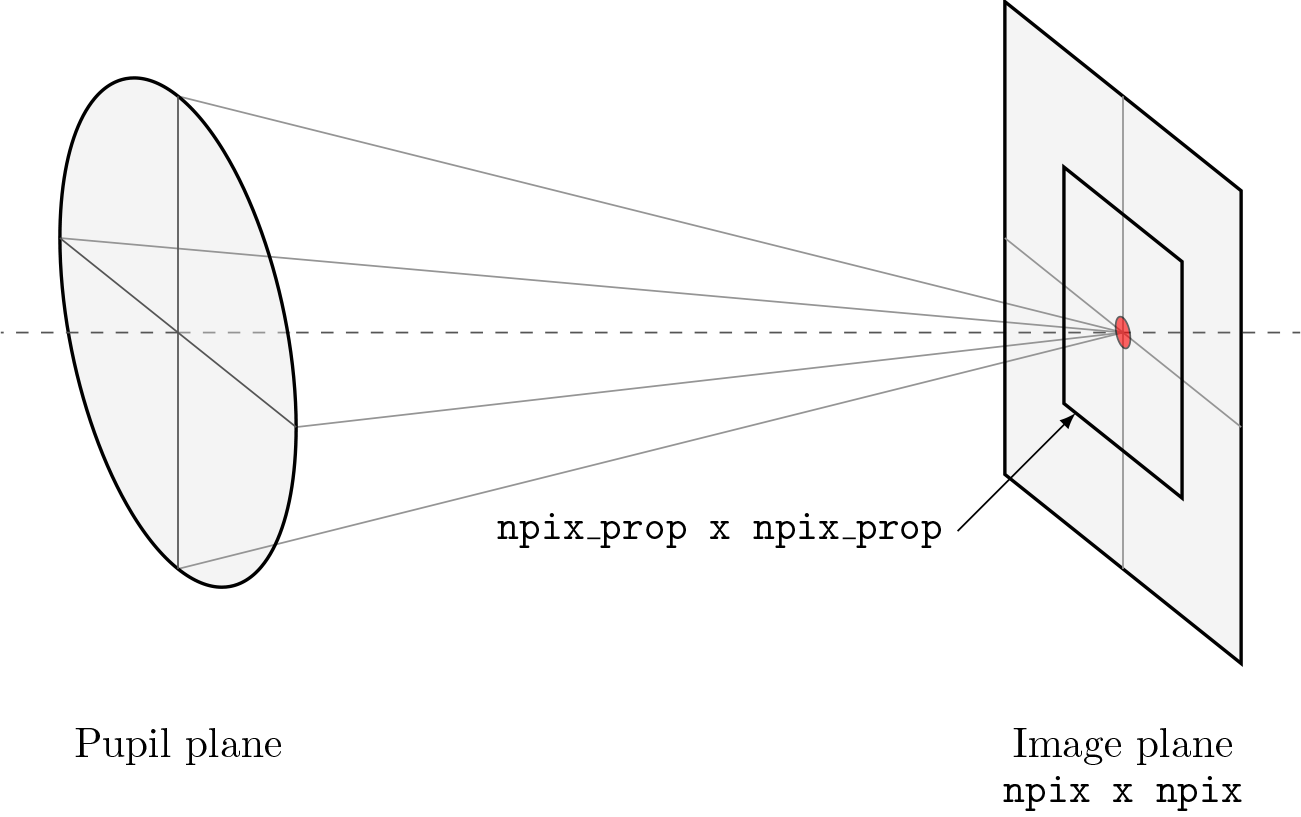
It can be advantageous to specify prop_shape < shape for performance
reasons, although care must be taken to ensure needed data is not accidentally
left out:
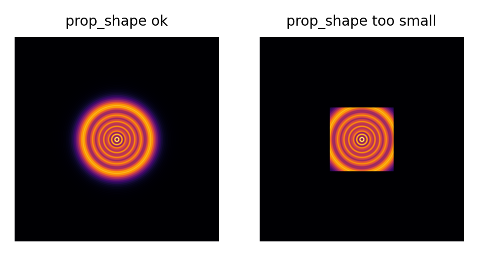
For most pupil to image plane propagations, setting prop_shape to 128 or 256
pixels provides an appropriate balance of performance and propagation plane size.
For image to pupil plane propagations, prop_shape must be sized to ensure
the pupil extent is adequately captured. Because the sampling constraints on
image to pupil plane propagations are typically looser, it is safest to let
prop_shape default to the same value as shape.
Discrete Fourier transform algorithms#
Most diffraction modeling tools use the Fast Fourier Transform (FFT) to evaluate the discrete Fourier transform (DFT) when propagating between planes. While the FFT provides great computational and memory efficiency, high-fidelity optical simulations may require working with exceptionally large zero-padded arrays to satisfy the sampling requirements imposed by the FFT.
Lentil implements a more general form of the DFT sometimes called the matrix triple product (MTP DFT) to perform the Fourier transform to propagate between planes. While the MTP DFT is slower than the FFT for same sized arrays, the MTP DFT provides independent control over the input and output plane sizing and sampling. This flexibility makes the MTP DFT ideally suited for performing propagations to discretely sampled image planes where it is often necessary to compute a finely sampled output over a relatively small number of pixels.
The chirp Z-transform provides additional efficiency when transforming large arrays. Lentil selects the most appropriate DFT method automatically based on the plane size and sampling requirements.
Sign of the DFT complex exponential#
Lentil adopts the convention that phasors rotate in the counter-clockwise direction, meaning their time dependence has the form \(\exp(-i\omega t)\). While this is an arbitrary choice, it matches the choice made in most classic optics texts. The implications of this choice are as follows:
Forward propagations use the DFT or FFT
Backward propagations use IDFT or IFFT. Note that Lentil does not currently support propagating backward through an optical system.
A converging spherical wave is represented by the expression \(\exp\left[-i\frac{k}{2z} (x^2 + y^2)\right]\)
A diverging spherical wave is represented by the expression \(\exp\left[i\frac{k}{2z} (x^2 + y^2)\right]\)